Status Up Protocol Down Serial
, My serial interface status is up but line protocol is down. can anyone tell me what is the , My serial interface status is up but line protocol is down.
Cisco switch Link status Up, Protocol down. R2 show interfaces serial 1/0. Serial1/0 is up, line protocol is down disabled Hardware is HD64570 MTU 1500.
Troubleshooting 'Line Protocol is Down' Problems on POS Interfaces
Cisco switch Link status Up, Protocol down. up vote 1 down vote favorite. R1 show interfaces serial 1/0. Serial1/0 is up, line protocol is up connected.

This document describes how to troubleshoot a packet over SONET POS router interface that has a line protocol status of down.
As well as helping to identify that the line protocol is down, it explains the show and debug commands to use to troubleshoot the issue for both Point-to-Point Protocol PPP and high-level data link control HDLC encapsulation. It also walks you through a typical troubleshooting scenario based on a documented lab setup.
Interpret the show interface pos Command
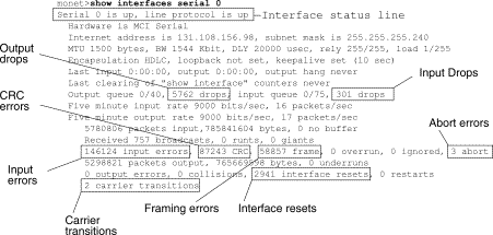
For the purposes of document, the output of show interface pos is as this output shows. Note the highlighted parts of the display and comments:
RTR12410-2 show interface pos 6/0
POS6/0 is up, line protocol is down
.--- The line protocol is down
MTU 4470 bytes, BW 2488000 Kbit, DLY 100 usec, rely 255/255, load 1/255
Encapsulation HDLC, crc 32, loopback not set
.--- The loopback has not been set.
.--- The keepalive is set as every ten seconds.
Last input never, output :05, output hang never
Last clearing of show interface counters never
Output queue 0/40, 0 drops; input queue 0/75, 0 drops
5 minute input rate 0 bits/sec, 0 packets/sec
5 minute output rate 0 bits/sec, 0 packets/sec
0 packets input, 0 bytes, 0 no buffer
Received 0 broadcasts, 0 runts, 0 giants, 0 throttles
0 input errors, 0 CRC, 0 frame, 0 overrun, 0 ignored, 0 abort
3 packets output, 1074 bytes, 0 underruns
0 output errors, 0 applique, 1 interface resets
0 output buffer failures, 0 output buffers swapped out
The Cisco IOS Command Reference states that the line protocol field status indicates whether the software processes that handle the line protocol consider the line usable that is, keepalives are successful or whether it has been taken down by an administrator.
Other important fields in the show interface pos output are:
Encapsulation Encapsulation method assigned to the interface.
loopback Indicates whether loopback is set.
keepalive Indicates whether keepalives are set.
This diagram illustrates the protocol stack used on a POS interface.
POS interfaces support multiple encapsulations - HDLC, PPP and Frame Relay. Thus, packet over SONET is more accurately PPP over SONET or HDLC over SONET. This document does not cover Frame Relay encapsulation.
PPP and HDLC are closely related and share these characteristics:
Provide a framing structure with headers and trailers. The trailer provides error checking.
Provide frame delineation, which defines for a receiver exactly where a packet and frame begins and ends. In HDLC and PPP, frame delineation is provided by means of a special interframe fill pattern or idle pattern. The pattern is 0x7E, or 0111 1110.
Define a minimum and maximum packet length.
Transport IP packets and provide a method for receivers to determine the precise type of packet inside the arriving frame.
However, although closely related, PPP and HDLC are not the same, and different debug commands are used to troubleshoot line protocol problems.
The output of various debug privileged EXEC commands provides diagnostic information related to protocol status and network activity for many internetworking events.
Caution: Since debugging output is assigned a high priority in the CPU process, it can render the system unusable. For this reason, use debug commands only to troubleshoot specific problems or during troubleshooting sessions with Cisco technical support staff. Moreover, it is best to use debug commands during periods of low network traffic and fewer users. Debugging during these periods decreases the likelihood that increased debug command processing overhead affects system use. When you finish using a debug command, remember to disable it with its specific no debug command or with the no debug all command.
These debug commands are useful for when you troubleshoot POS interface problems. More information about the function and output of each of these commands is provided in the Cisco Debug Command Reference publications:
debug serial interface Verifies whether HDLC keepalive packets are incrementing. If they are not, a possible timing problem exists on the interface card or in the network.
debug ppp negotiation Shows PPP packets transmitted during PPP startup, where PPP options are negotiated.
debug ppp packet Shows PPP packets being sent and received. This command displays low-level packet dumps.
debug ppp errors Shows PPP errors such as illegal or malformed frames associated with PPP connection negotiation and operation.
Refer to Troubleshooting Serial Line Problems for more information.
Line Protocol Is Down With HDLC
HDLC is the default encapsulation type on a POS router interface. HDLC is an international standard, but vendor implementations vary one or more fields or the header or trailer in size and format. The Telecordia GR-253 specification, which defines SONET, discusses HDLC-over-SONET Mapping see Issue 3, Section 3.4.2.3, pp.3-59. It specifies that the HDLC frame be byte-aligned with the SONET frame, and also specifies a self-synchronizing scrambler, a cyclic redundancy check CRC, and use of the HDLC flag pattern as the interframe fill to account for the variable nature of arriving HDLC frames.
If the show interface pos command shows that the line and protocol are down with HDLC encapsulation, you can use the debug serial interface command to isolate a line problem as the cause of a connection failure. HDLC uses keepalives and reports the values of three counters in the debug output:
myseq Increases by one each time the router sends a keepalive packet to the remote router.
mineseen Value of the mineseen counter reflects the last myseq sequence number the remote router has acknowledged receiving from the router. The remote router stores this value in its yourseen counter and sends that value in a keepalive packet to the router.
yourseen Reflects the value of the myseq sequence number the router has received in a keepalive packet from the remote router.
If the keepalive values in the mineseq, yourseen, and myseen fields are not incrementing in each subsequent line of output, there is a problem at one end of the connection. When the difference in the values in the myseq and mineseen fields exceeds three, the line goes down and the interface is reset.
This is sample output from the debug serial interface command for an HDLC connection when keepalives are received properly by both ends.
hswan-12008-2a debug serial interface
Serial network interface debugging is on
Oct 31 :16: POS4/0: HDLC myseq 180, mineseen 0, yourseen 1, line up
Oct 31 :17: LINEPROTO-5-UPDOWN: Line protocol on Interface POS4/0,
.--- Local router sees a remote keepalive with a sequence number of 1.
Oct 31 :26: POS4/0: HDLC myseq 181, mineseen 181, yourseen 2, line up
Oct 31 :36: POS4/0: HDLC myseq 182, mineseen 182, yourseen 3, line up
Oct 31 :46: POS4/0: HDLC myseq 183, mineseen 183, yourseen 4, line up
Oct 31 :56: POS4/0: HDLC myseq 184, mineseen 184, yourseen 5, line up
Oct 31 :06: POS4/0: HDLC myseq 185, mineseen 185, yourseen 6, line up
.--- Keepalives are sent every 10 seconds by default.. --- Both sides report incrementing sequence numbers.
This is sample output from the debug serial interface command for an HDLC connection when the remote interface is shut and the local interface misses more than three keepalives.
Oct 31 :46: POS4/0: HDLC myseq 195, mineseen 192, yourseen 13, line down
Oct 31 :47: LINEPROTO-5-UPDOWN: Line protocol on Interface POS4/0,
.--- The local router has failed to receive three keepalives and. --- brings down the line protocol. Note the difference between. --- myseq 195 and mineseen 192.
Oct 31 :56: POS4/0: HDLC myseq 196, mineseen 192, yourseen 13, line down
Oct 31 :06: POS4/0: HDLC myseq 197, mineseen 192, yourseen 13, line down
Oct 31 :16: POS4/0: HDLC myseq 198, mineseen 192, yourseen 13, line down
Oct 31 :26: POS4/0: HDLC myseq 199, mineseen 192, yourseen 13, line down
Oct 31 :36: POS4/0: HDLC myseq 200, mineseen 0, yourseen 1, line up
Oct 31 :37: LINEPROTO-5-UPDOWN: Line protocol on Interface POS4/0,
.--- After you execute the no shut command on the remote router. --- the local router receives a keepalive again and brings up. --- the line protocol.
Oct 31 :46: POS4/0: HDLC myseq 201, mineseen 201, yourseen 2, line up
Oct 31 :56: POS4/0: HDLC myseq 202, mineseen 202, yourseen 3, line up
Oct 31 :06: POS4/0: HDLC myseq 203, mineseen 203, yourseen 4, line up
Oct 31 :16: POS4/0: HDLC myseq 204, mineseen 204, yourseen 5, line up
Oct 31 :26: POS4/0: HDLC myseq 205, mineseen 205, yourseen 6, line up
Oct 31 :36: POS4/0: HDLC myseq 206, mineseen 206, yourseen 7, line up
.--- After the shut/no shut, the remote router re-initialized its. --- sequence number.
Line Protocol Is Down With PPP
RFC 1661 defines PPP as a protocol. POS interfaces support PPP in High-Level Data Link Control HDLC -like framing, as specified in RFC 1662, for data encapsulation at Layer 2. The frame format for PPP in HDLC-like framing is shown in this figure.
RFC 2615 specifies the use of PPP encapsulation over SONET or SDH links. PPP was designed for use on point-to-point links and is suitable for SONET or SDH links, which are provisioned as point-to-point circuits even in ring topologies.
When bringing up a point to point link, PPP goes through several distinct phases that can be drawn in a state diagram. When an external event, such as carrier detection or network administrator configuration, indicates that the physical layer is ready to be used, PPP proceeds to the link establishment phase. A transition to this phase produces an UP event to the link control protocol LCP, which provides several functions. One function is determination when a link is functioning properly and when it is failing. In order to establish communication over a point-to-point link, each end of the PPP link must first send LCP packets to configure and test the data link.
Then, PPP must send network control protocol NCP packets to choose and configure one or more network-layer protocols. Once each of the chosen network-layer protocols has been configured, datagrams from each network-layer protocol can be sent over the link.
This table lists the three classes of LCP packets:
Configure-Request, Configure-Ack, Configure-Nak and Configure-Reject
Used to establish and configure a link.
Terminate-Request and Terminate-Ack
Code-Reject, Protocol-Reject, Echo-Request, Echo-Reply, and Discard-Request
Used to manage and debug a link.
LCP is used to establish the connection through an exchange of Configure packets. This exchange is complete, and the LCP Opened state entered, once a Configure-Ack packet has been both sent and received.
This sample output captures the LCP link configuration stage on a POS interface:
4d01h: PO3/1 LCP: State is Open
4d01h: PO3/1 PPP: I pkt type 0x8021, datagramsize 14 LCP_UP
0x639FCAD8 id 0 0s. queued 1/1/2
4d01h: PO3/1 PPP: Phase is UP
4d01h: PO3/1 IPCP: O CONFREQ Closed id 152 len 10
4d01h: PO3/1 IPCP: Address 172.16.1.1 0x0306AC100101
4d01h: PO3/1 PPP: I pkt type 0x8021, datagramsize 14
4d01h: PO3/1 IPCP: I CONFREQ REQsent id 1 len 10
4d01h: PO3/1 IPCP: Address 172.16.1.2 0x0306AC100102
4d01h: PO3/1 IPCP: O CONFACK REQsent id 1 len 10
4d01h: PO3/1 IPCP: I CONFACK ACKsent id 152 len 10
4d01h: PO3/1 IPCP: State is Open
4d01h: PO3/1 IPCP: Install route to 172.16.1.2
4d01h: LINEPROTO-5-UPDOWN: Line protocol on Interface POS3/1,
Note: A POS interface configured with PPP encapsulation continually tries to establish a PPP session. Thus, you see the line protocol come up briefly on a periodic basis when there is a sustained problem, even when the fiber is removed.
Link Maintenance With Keepalives
LCP Echo-Request and Echo-Reply packets provide a Layer 2 loopback mechanism for both directions of the link. On reception of an Echo-Request in the LCP Opened state, an Echo-Reply must be transmitted.
This diagram from RFC 1661 illustrates the format of a PPP keepalive packet.
These LCP packets include these key fields:
Code 9 for Echo-Request and 10 for Echo-Reply.
Identifier On transmission, the Identifier field must be changed whenever the content of the Data field changes and whenever a valid reply has been received for a previous request. For retransmissions, the Identifier may remain unchanged. On reception, the Identifier field of the Echo-Request is copied into the Identifier field of the Echo-Reply packet.
Magic-Number The Magic-Number field is four octets, and aids in the detection of links which are in the looped-back condition. Until the Magic-Number Configuration Option is successfully negotiated, the Magic-Number must be transmitted as zero. See the Magic-Number Configuration Option in RFC 1661 for further explanation.
Data The Data field is zero or more octets, and contains uninterpreted data for use by the sender. The data may consist of any binary value. The end of the field is indicated by the Length.
Here is an example of debug ppp negotiation when keepalives are enabled:
4d01h: PO3/1 LCP: O ECHOREQ Open id 1 len 12 magic 0x1A45933B
4d01h: PO3/1 PPP: I pkt type 0xC021, datagramsize 16
4d01h: PO3/1 LCP: I ECHOREP Open id 1 len 12 magic 0x00000002
4d01h: PO3/1 LCP: Received id 1, sent id 1, line up
PPP can terminate the link at any time. Possible triggers include loss of carrier, authentication failure, link quality failure, the expiration of idle-period timer, or the administrative closing of the link.
LCP uses Terminate packets to close the link. The sender of the Terminate-Request should disconnect after receiving a Terminate-Ack, or after the Restart counter expires. The receiver of a Terminate-Request should wait for the peer to disconnect, and must not disconnect until at least one Restart time has passed after sending a Terminate-Ack.
Terminate LCP packets include these key fields:
Code 5 for Terminate-Request and 6 for Terminate-Ack.
Identifier On transmission, the Identifier field must be changed whenever the content of the Data field changes, and whenever a valid reply has been received for a previous request. For retransmissions, the Identifier can remain unchanged. On reception, the Identifier field of the Terminate-Request is copied into the Identifier field of the Terminate-Ack packet.
The Data field is zero or more octets, and contains uninterpreted data for use by the sender. The data can consist of any binary value. The end of the field is indicated by the Length.
Here is an example of debug ppp negotiation output when you receive a TERMREQ packet:
4d01h: PO3/1 PPP: I pkt type 0xC021, datagramsize 8
4d01h: PO3/1 LCP: I TERMREQ Open id 4 len 4
4d01h: PO3/1 LCP: O TERMACK Open id 4 len 4
4d01h: PO3/1 PPP: I pkt type 0xC021, datagramsize 18
4d01h: PO3/1 IPCP: State is Closed
4d01h: PO3/1 PPP: Phase is TERMINATING
4d01h: PO3/1 LCP: I CONFREQ TERMsent id 1 len 14
4d01h: PO3/1 LCP: MRU 1500 0x010405DC
4d01h: PO3/1 LCP: MagicNumber 0x00000002 0x050600000002
4d01h: PO3/1 LCP: Dropping packet, state is TERMsent
.--- While in the TERMsent state, PPP should drop all other packets.
4d01h: PO3/1 IPCP: Remove route to 172.16.1.2
Sample Troubleshooting Sequence
This section describes a sample troubleshooting scenario for a POS link using PPP encapsulation. It uses these configurations:
ip address 1.1.1.6 255.255.255.0
ip address 1.1.1.5 255.255.255.0
Note: These debugs were captured on two routers in a back-to-back lab setup. Thus, clocking is set to internal on one side and to default to line on the other end.
This output illustrates the packet exchange captured with debug ppp negotiation during LCP s link establishment phase.
.--- The router sends an outgoing confreq.
Nov 7 :00: LINK-3-UPDOWN: Interface POS1/0, changed state to up
Nov 7 :00: PO1/0 PPP: Treating connection as a dedicated line
Nov 7 :00: PO1/0 PPP: Phase is ESTABLISHING, Active Open
Nov 7 :00: PO1/0 LCP: O CONFREQ Closed id 7 len 14
Nov 7 :00: PO1/0 LCP: MRU 4470 0x01041176
Nov 7 :00: PO1/0 LCP: MagicNumber 0x4F46AF4D 0x05064F46AF4D
.--- Router A receives an incoming confreq from router B.
Nov 7 :00: PO1/0 LCP: I CONFREQ REQsent id 45 len 14
Nov 7 :00: PO1/0 LCP: MagicNumber 0x2631E6D2 0x05062631E6D2
.--- Router A responds with a confack and receives a. --- confack from Router B. The LCP state is open.
Nov 7 :00: PO1/0 LCP: O CONFACK REQsent id 45 len 14
Nov 7 :00: PO1/0 LCP: I CONFACK ACKsent id 7 len 14
Nov 7 :00: PO1/0 LCP: State is Open
Nov 7 :00: PO1/0 PPP: Phase is UP
.--- Router A begins the IPCP stage and negotiates an IP address.. --- In this setup, the peer router already has an address and. --- sends it in a confreq. If the peer router accepts the address. --- it responds with a confack.
Nov 7 :00: PO1/0 IPCP: O CONFREQ Closed id 7 len 10
Nov 7 :00: PO1/0 IPCP: Address 1.1.1.6 0x030601010106
Nov 7 :00: PO1/0 CDPCP: O CONFREQ Closed id 7 len 4
Nov 7 :00: PO1/0 IPCP: I CONFREQ REQsent id 9 len 10
Nov 7 :00: PO1/0 IPCP: Address 1.1.1.5 0x030601010105
Nov 7 :00: PO1/0 IPCP: O CONFACK REQsent id 9 len 10
Nov 7 :00: PO1/0 CDPCP: I CONFREQ REQsent id 9 len 4
Nov 7 :00: PO1/0 CDPCP: O CONFACK REQsent id 9 len 4
Nov 7 :00: PO1/0 IPCP: I CONFACK ACKsent id 7 len 10
Nov 7 :00: PO1/0 IPCP: State is Open
Nov 7 :00: PO1/0 CDPCP: I CONFACK ACKsent id 7 len 4
Nov 7 :00: PO1/0 CDPCP: State is Open
Nov 7 :00: PO1/0 IPCP: Install route to 1.1.1.5
Nov 7 :01: LINEPROTO-5-UPDOWN: Line protocol on
Interface POS1/0, changed state to up
.--- Router B receives an incoming confrq from Router A.
Nov 7 :19.043: PO2/0 LCP: I CONFREQ Open id 7 len 14
Nov 7 :19.043: PO2/0 LCP: MRU 4470 0x01041176
Nov 7 :19.043: PO2/0 LCP: MagicNumber 0x4F46AF4D 0x05064F46AF4D
Nov 7 :19.043: PO2/0 IPCP: State is Closed
Nov 7 :19.043: PO2/0 CDPCP: State is Closed
Nov 7 :19.043: PO2/0 PPP: Phase is TERMINATING
Nov 7 :19.043: PO2/0 PPP: Phase is ESTABLISHING
.--- Router B sends its own LCP confreq.
Nov 7 :19.043: PO2/0 LCP: O CONFREQ Open id 45 len 14
Nov 7 :19.043: PO2/0 LCP: MagicNumber 0x2631E6D2 0x05062631E6D2
.--- Router B responds with a confack and receives a confack from Router A.
Nov 7 :19.043: PO2/0 LCP: O CONFACK Open id 7 len 14
Nov 7 :19.043: PO2/0 IPCP: Remove route to 1.1.1.6
Nov 7 :19.047: PO2/0 LCP: I CONFACK ACKsent id 45 len 14
Nov 7 :19.047: PO2/0 LCP: MRU 4470 0x01041176
Nov 7 :19.047: PO2/0 LCP: MagicNumber 0x2631E6D2 0x05062631E6D2
Nov 7 :19.047: PO2/0 LCP: State is Open
Nov 7 :19.047: PO2/0 PPP: Phase is UP
.--- Router B also begins the IPCP stage and negotiates an IP address.
Nov 7 :19.047: PO2/0 IPCP: O CONFREQ Closed id 9 len 10
Nov 7 :19.047: PO2/0 IPCP: Address 1.1.1.5 0x030601010105
Nov 7 :19.047: PO2/0 CDPCP: O CONFREQ Closed id 9 len 4
Nov 7 :19.047: PO2/0 IPCP: I CONFREQ REQsent id 7 len 10
Nov 7 :19.047: PO2/0 IPCP: Address 1.1.1.6 0x030601010106
Nov 7 :19.047: PO2/0 IPCP: O CONFACK REQsent id 7 len 10
Nov 7 :19.047: PO2/0 CDPCP: I CONFREQ REQsent id 7 len 4
Nov 7 :19.047: PO2/0 CDPCP: O CONFACK REQsent id 7 len 4
Nov 7 :19.047: PO2/0 IPCP: I CONFACK ACKsent id 9 len 10
Nov 7 :19.047: PO2/0 IPCP: State is Open
Nov 7 :19.047: PO2/0 CDPCP: I CONFACK ACKsent id 9 len 4
Nov 7 :19.047: PO2/0 CDPCP: State is Open
Nov 7 :19.047: PO2/0 IPCP: Install route to 1.1.1.6
Nov 7 :19.048: LINEPROTO-5-UPDOWN: Line protocol on
Interface POS2/0, changed state to up
This output illustrates the packet exchange captured with debug ppp packet while a link is being established. This debug captures the value of the protocol field in the PPP packet. RFC 1661 defines the Protocol field as one or two octets. The value in this field identifies the datagram encapsulated in the Information field of the packet.
Protocol field values in the 0 to 3 range identify the network-layer protocol of specific packets, and values in the 8 to b range identify packets belonging to the associated Network Control Protocols NCPs, if any. Protocol field values in the c to f range identify packets as link-layer Control Protocols such as LCP. There also are various vendor-specific values. Click here for a complete list of PPP protocol field values.
Nov 7 :58: PO1/0 PPP: I pkt type 0xC021, datagramsize 18
Nov 7 :58: PO1/0 LCP: I CONFREQ Closed id 7 len 14
Nov 7 :58: PO1/0 LCP: MRU 4470 0x01041176
Nov 7 :58: PO1/0 LCP: MagicNumber 0x269933F4 0x0506269933F4
Nov 7 :58: PO1/0 LCP: O CONFREQ Closed id 57 len 14 Z
Nov 7 :58: PO1/0 LCP: MagicNumber 0x4FAE1B0C 0x05064FAE1B0C
Nov 7 :58: PO1/0 LCP: O CONFACK REQsent id 7 len 14
Nov 7 :58: LINK-3-UPDOWN: Interface POS1/0, changed state to up
Nov 7 :58: PO1/0 LCP: I CONFACK ACKsent id 57 len 14ppp
Nov 7 :58: PO1/0 PPP: I pkt type 0x8021, datagramsize 14
.--- 0x8021 identifies IPCP, PPP internet protcol control protocol.
Nov 7 :58: PO1/0 PPP: I pkt type 0x8207, datagramsize 8
.--- 0x8207 identifies Cisco discovery protocol control.
Nov 7 :58: PO1/0 IPCP: O CONFREQ Closed id 15 len 10
Nov 7 :58: PO1/0 IPCP: Address 1.1.1.6 0x030601010106
Nov 7 :58: PO1/0 CDPCP: O CONFREQ Closed id 13 len 4
Nov 7 :58: PO1/0 IPCP: I CONFREQ REQsent id 14 len 10packet
Nov 7 :58: PO1/0 IPCP: Address 1.1.1.5 0x030601010105
Nov 7 :58: PO1/0 IPCP: O CONFACK REQsent id 14 len 10
Nov 7 :58: PO1/0 CDPCP: I CONFREQ REQsent id 15 len 4
Nov 7 :58: PO1/0 CDPCP: O CONFACK REQsent id 15 len 4
Nov 7 :58: PO1/0 IPCP: I CONFACK ACKsent id 15 len 10
Nov 7 :58: PO1/0 CDPCP: I CONFACK ACKsent id 13 len 4
Nov 7 :59: PO1/0 PPP: I pkt type 0x0207, datagramsize 376
.--- 0x0207 identifies Cisco Discovery Protocol CDP.
Nov 7 :59: LINEPROTO-5-UPDOWN: Line protocol on Interface
.--- ECHOREQand ECHOREP packets for PPP keepalives use packet type values. --- of 0xC021.
Nov 7 :05: PO1/0 PPP: I pkt type 0xC021, datagramsize 16
Nov 7 :05: PO1/0 LCP: I ECHOREQ Open id 1 len 12 magic 0x269933F4
Nov 7 :05: PO1/0 LCP: O ECHOREP Open id 1 len 12 magic 0x4FAE1B0C
Nov 7 :07: PO1/0 LCP: O ECHOREQ Open id 1 len 12 magic 0x4FAE1B0C
Nov 7 :07: PO1/0 PPP: I pkt type 0xC021, datagramsize 16
Nov 7 :07: PO1/0 PPP: O pkt type 0x0207, datagramsize 376
Nov 7 :07: PO1/0 LCP: I ECHOREP Open id 1 len 12 magic 0x269933F4
Nov 7 :07: PO1/0 LCP: Received id 1, sent id 1, line up
Nov 7 :16.947: PO2/0 PPP: I pkt type 0xC021, datagramsize 18
Nov 7 :16.947: PO2/0 LCP: I CONFREQ REQsent id 57 len 14
Nov 7 :16.947: PO2/0 LCP: MRU 4470 0x01041176
Nov 7 :16.947: PO2/0 LCP: MagicNumber 0x4FAE1B0C 0x05064FAE1B0C
Nov 7 :16.947: PO2/0 LCP: O CONFACK REQsent id 57 len 14
Nov 7 :16.947: PO2/0 LCP: I CONFACK ACKsent id 7 len 14
Nov 7 :16.947: PO2/0 LCP: MagicNumber 0x269933F4 0x0506269933F4
Nov 7 :16.947: PO2/0 IPCP: O CONFREQ Closed id 14 len 10
Nov 7 :16.947: PO2/0 IPCP: Address 1.1.1.5 0x030601010105
Nov 7 :16.947: PO2/0 CDPCP: O CONFREQ Closed id 15 len 4
Nov 7 :16.947: PO2/0 PPP: I pkt type 0x8021, datagramsize 14
Nov 7 :16.951: PO2/0 PPP: I pkt type 0x8207, datagramsize 8
Nov 7 :16.951: PO2/0 IPCP: I CONFREQ REQsent id 15 len 10
Nov 7 :16.951: PO2/0 IPCP: Address 1.1.1.6 0x030601010106
Nov 7 :16.951: PO2/0 IPCP: O CONFACK REQsent id 15 len 10
Nov 7 :16.951: PO2/0 PPP: I pkt type 0x8021, datagramsize 14
Nov 7 :16.951: PO2/0 CDPCP: I CONFREQ REQsent id 13 len 4
Nov 7 :16.951: PO2/0 CDPCP: O CONFACK REQsent id 13 len 4
Nov 7 :16.951: PO2/0 IPCP: I CONFACK ACKsent id 14 len 10
Nov 7 :16.951: PO2/0 IPCP: Address 1.1.1.5 0x030601010105
Nov 7 :16.951: PO2/0 CDPCP: I CONFACK ACKsent id 15 len 4
Nov 7 :17.947: LINEPROTO-5-UPDOWN: Line protocol on Interface POS2/0,
.--- ECHOREQ and ECHOREP packets for PPP keepalives use packet type. --- values of 0xC021.
Nov 7 :17.947: PO2/0 PPP: O pkt type 0x0207, datagramsize 376
Nov 7 :23.403: PO2/0 LCP: O ECHOREQ Open id 1 len 12 magic 0x269933F4
Nov 7 :23.403: PO2/0 PPP: I pkt type 0xC021, datagramsize 16
Nov 7 :23.403: PO2/0 LCP: I ECHOREP Open id 1 len 12 magic 0x4FAE1B0C
Nov 7 :23.403: PO2/0 LCP: Received id 1, sent id 1, line up
Nov 7 :25.595: PO2/0 PPP: I pkt type 0xC021, datagramsize 16
A POS interface with PPP or HDLC encapsulation supports two mechanisms to alert you of a link failure: Layer 2 keepalives and SONET-layer alarms. Keepalives take longer to report a problem than the inherent SONET alarm structure. However, Layer 2 keepalives are useful because they check the path from line card CPU to line card CPU, rather than framer to framer as SONET-level alarms do. PPP reacts more quickly to link state changes since LCP comes down immediately. In contrast, HDLC must time out the keepalives.
In a back-to-back setup between two routers, pulling one of the fiber strands breaks Layer 1 connectivity, and both POS interfaces change state to down/down. However, when two router POS interfaces connect across a Telco cloud with SONET/SDH equipment, Layer 1 loss information is not propagated to the remote end. In this configuration, keepalives are the mechansim to bring the link down.
Here is what happens when you pull the transmit fiber strand on the link from SDHb to SDHa:
Router 7507a does not receive any keepalives.
Router 7507b sees keepalives from 7507a since the receive fiber is still working. Use debug serial interface to confirm this.
Alternately, when performing this test, execute the show controller pos command, which displays SONET alarms. You should see a path alarm indication signal P-AIS on router 7507a and a path remote defect indication P-RDI on 7507b.
If the output of the show interfaces pos command indicates that the serial line is up but the line protocol is down, use loopback tests to determine the source of the problem. Perform a local loop test first, and then a remote test. Refer to Understanding Loopback Modes on Cisco Routers for guidance.
Note: Change the encapsulation from PPP to HDLC when you use loopbacks. The line protocol on an interface configured with PPP comes up only when all LCP and NCP sessions are negotiated successfully.
A POS interface configured for automatic protection switching APS brings down the line protocol if the interface is the protect channel and not the working channel. Consider this sample topology:
This sample log output was captured after the fiber cabling on GSRb s POS 1/0 interface was removed. Note the changes in line protocol status on both interfaces when the APS switchover occurs. Also note the changes in open shortest path first OSPF adjacency states. Refer to the APS Technology Support Page for more information.
Sep 5 :46: SONET-4-ALARM: POS1/0: SLOS
Sep 5 :46: SONET-4-ALARM: POS2/0: APS enabling channel
Sep 5 :46: SONET-6-APSREMSWI: POS2/0: Remote APS status now Protect
Sep 5 :46: SONET-4-ALARM: POS1/0: APS disabling channel
Sep 5 :46: LINEPROTO-5-UPDOWN: Line protocol on Interface POS2/0,
Sep 5 :46: LINEPROTO-5-UPDOWN: Line protocol on Interface POS1/0,
Sep 5 :48: LINK-3-UPDOWN: Interface POS1/0, changed state to down
Sep 5 :48: OSPF-5-ADJCHG: Process 1, Nbr 192.168.100.100 on POS1/0
from FULL to DOWN, Neighbor Down: Interface down or detached
Sep 5 :56: OSPF-5-ADJCHG: Process 1, Nbr 192.168.100.100 on POS2/0
from LOADING to FULL, Loading Done
Avoid configuring APS on a POS interface with PPP encapsulation. PPP is not aware of APS. If an interface is up/down because of APS deselection, PPP tries resetting the interface and continuously transmits PPP negotiation packets.
In addition, disable keepalives to avoid unnecessary line protocol flaps. Keepalives are disabled automatically on most POS router hardware.
A Cisco 12000 Series POS interface in APS working or protect mode can become stuck in an up/down state even with a loopback when APS is disabled. Another card inserted in the same slot experiences this problem. Move the card to a new slot to restore proper line-protocol status. This problem is resolved in Cisco IOS Software Release 12.0 19 S under Cisco bug ID CSCdt43759 registered customers only .
Use these steps as a workaround:
Configure the aps protect command.
Issue the aps force 1 command.
Configure the no aps protect command.
Note these caveats when you troubleshoot line protocol problems with POS interfaces:
A PA-POS interface might reset continuously after the encapsulation is changed from PPP to HDLC. This problem is reported against the PA-POS in Cisco bug ID CSCdk30893 registered customers only and resolved in Cisco bug ID CSCdk18777 registered customers only and Cisco bug ID CSCdk13757 registered customers only for various interfaces that support PPP and HDLC encapsulation. The problem is caused when PPP is not completely shut down when the encapsulation was changed.
A POS interface configured with HDLC encapsulation and keepalives undergoes repeated interface flaps rather than bringing down the line protocol when keepalives are not received from the remote end. This problem is resolved in Cisco bug ID CSCdp86387 registered customers only .
- Serial x is up, line protocol is up This is the proper status line condition. No action is required. Serial x is down, line protocol is down DTE 1 mode.
- POS router interface that has a line protocol status of down. 6/0 POS6/0 is up, line protocol is down debug serial interface Serial network.
